Engineering company «GazSurf»
Moscow, Volokolamsk highway, 1, building 1
+7 (495) 929 71 48 | info@gazsurf.com
Engineering company «GazSurf»
Moscow, Volokolamsk highway, 1, building 1
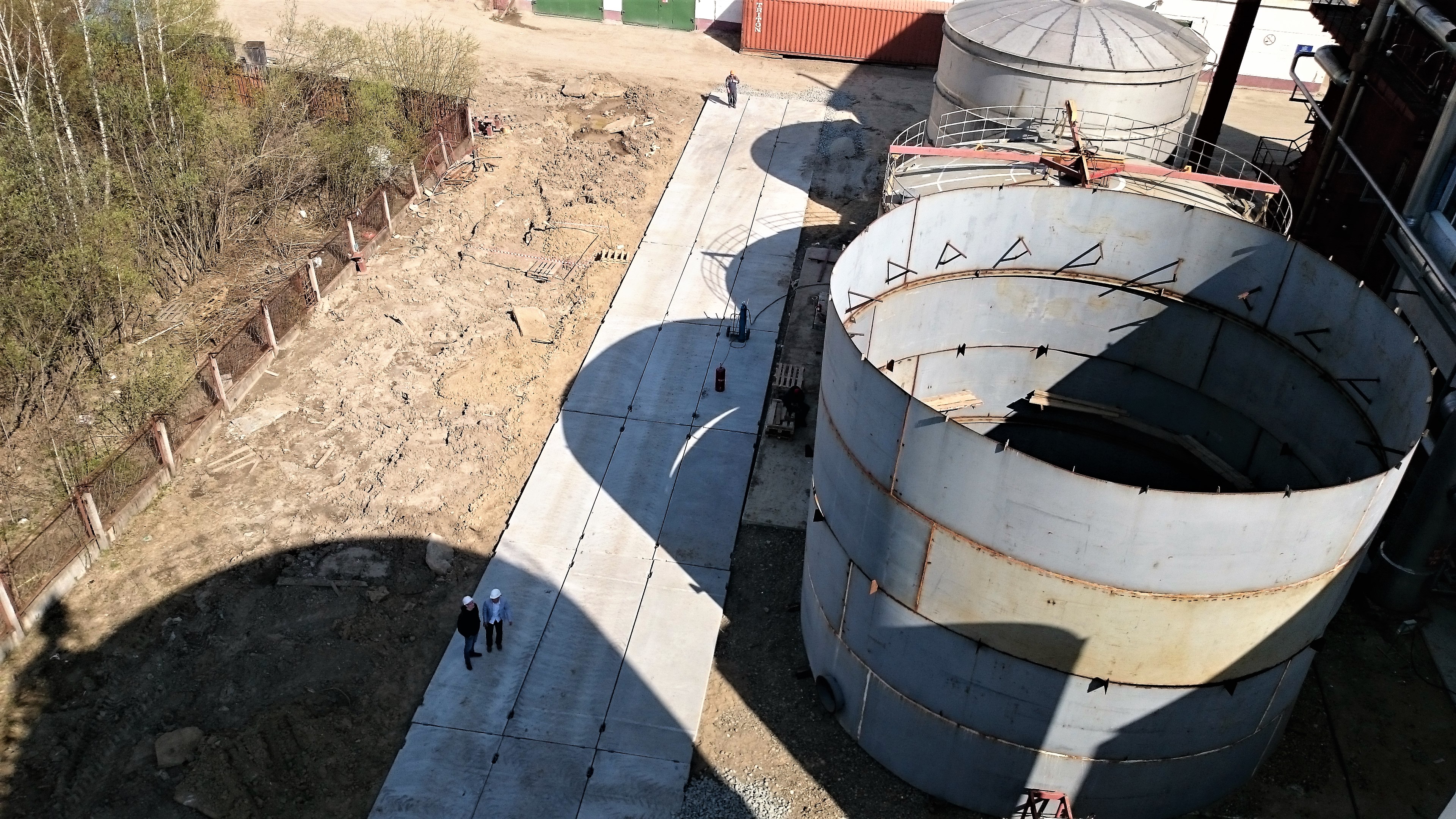
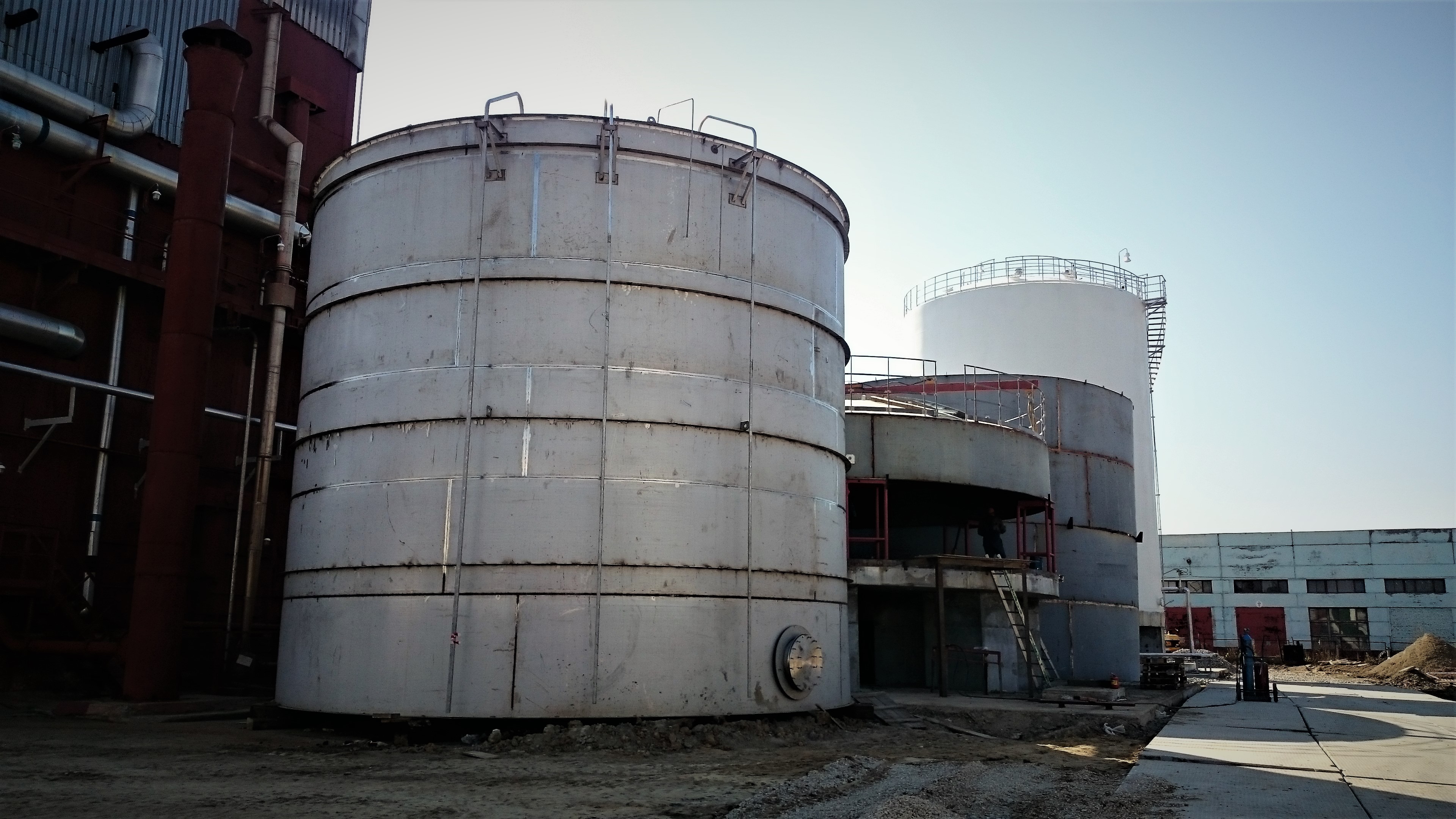
500 scm liquid oxygen storage cryogenic tank construction
Customer: PAO "Cryogenmash"
End user: Tomsk affiliate "Cryogenmash-Gas" affiliate
Site location: Tomsk region, Tomsk, Kuzovlevskiy trakt, 2-384
Scope of works: Design, equipment procurement, supervision of installation, systems and integrated testing, start up and commissioning
Cryogenic reservoir for О2 storage
Flat bottom cryogenic tank has several purposes:
- to receive liquid oxygen produced at the air separation unit;
- to provide long-term storage capabilities of liquid oxygen product;
- to manage liquid oxygen distribution to the product discharge pumps (centrifugal and reciprocating);
- to fill the product to the tanker trucks as well as to receive the liquid oxygen product from the tanker trucks.
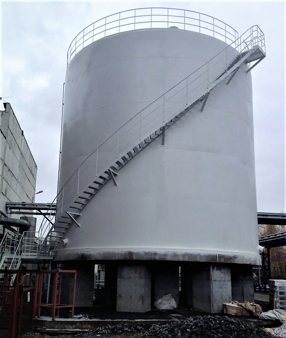
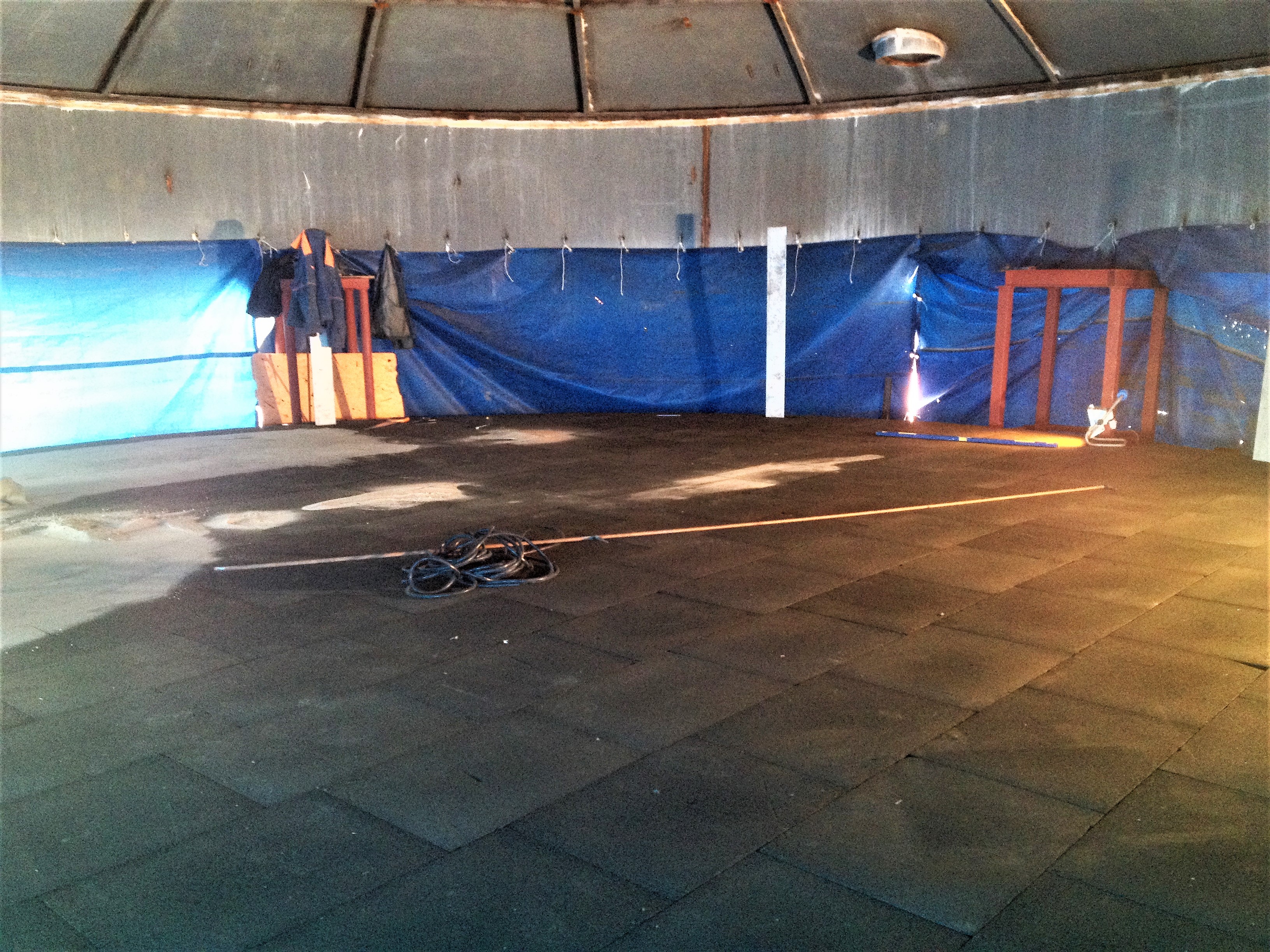
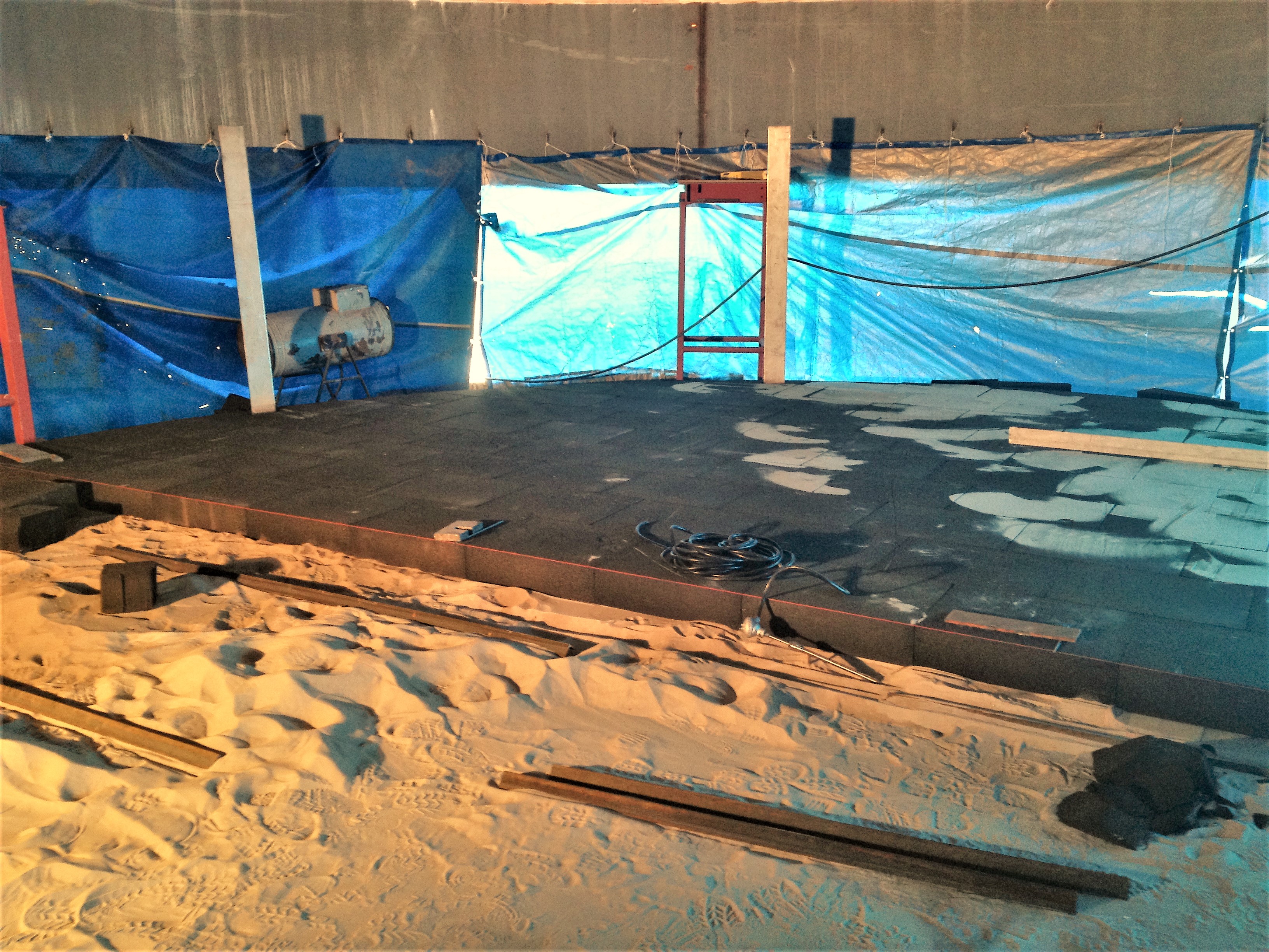
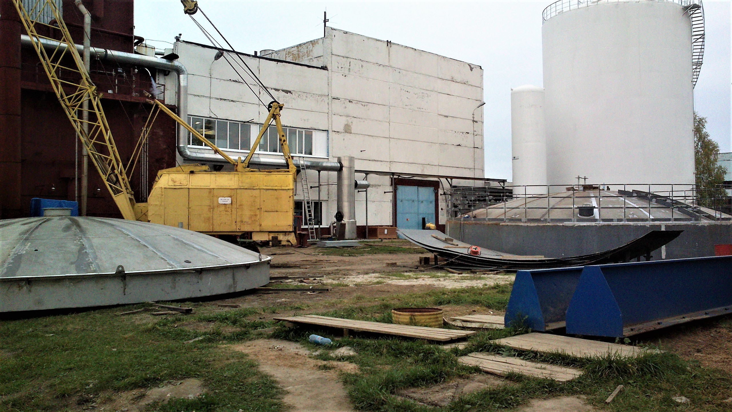
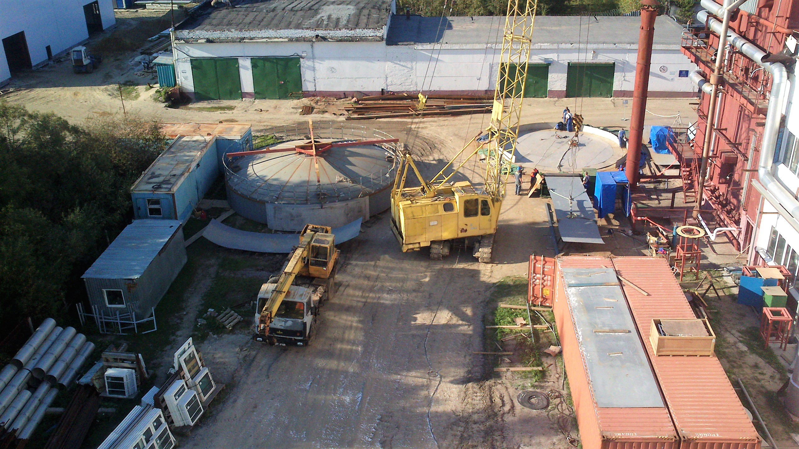
Cryogenic tank construction
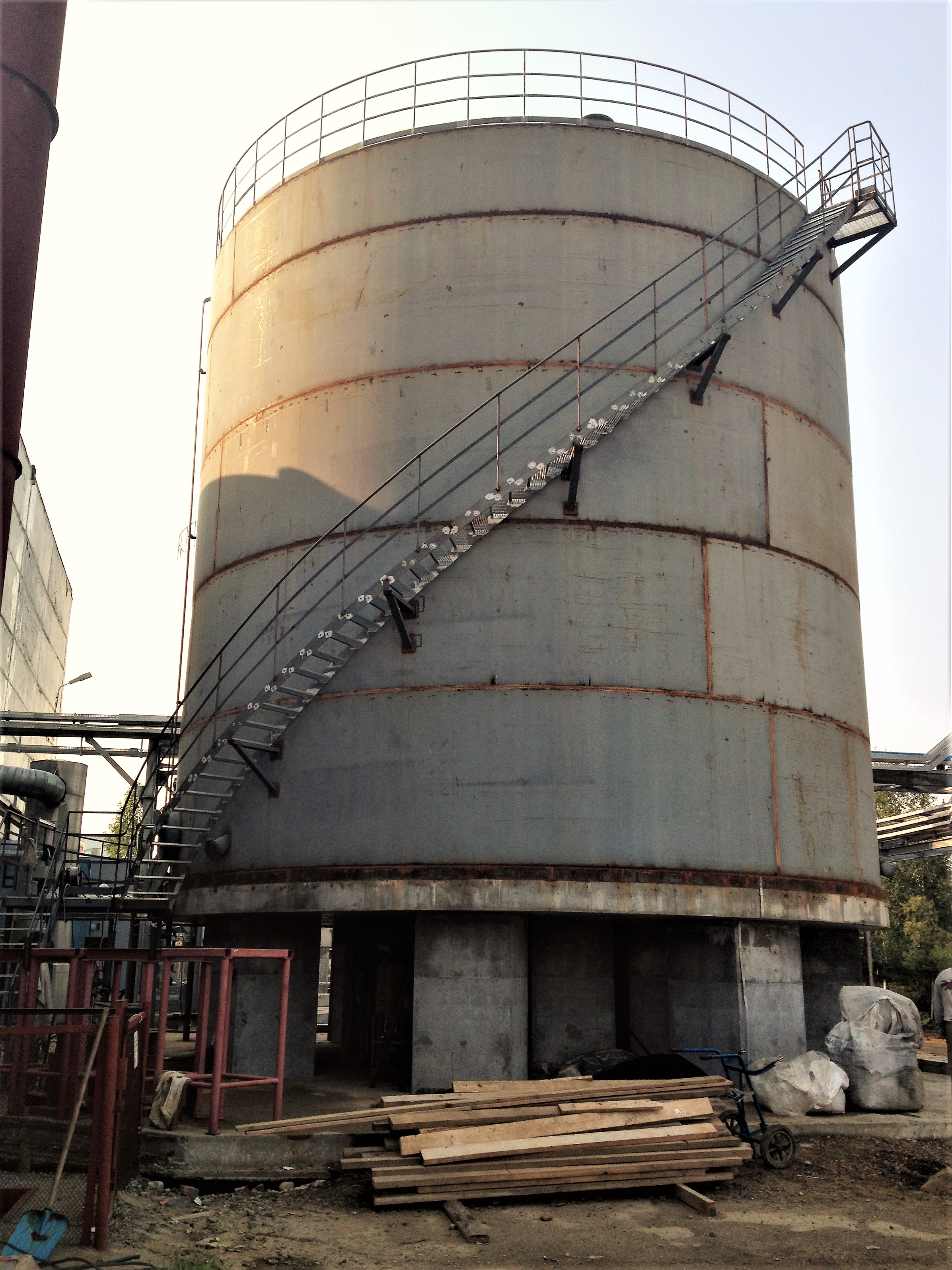
From the construction standpoint the cryogenic reservoir consists of the inner vessel and outer jacket. An inner vessel is manufactured out of the austenitic alloy-treated steel while the jacket is made out of carbon steel. Both the inner vessel and the outer jacket are attached to the foundation via the base plates that are embedded into the cement pouring during the foundation works.
Thermoinsulating wall spacing between the inner vessel and the outer jacket is filled with thermoinsulating material – expanded perlite powder.
Thermoinsulation between the bottom of the tank and the foundation is achieved with the layer of foamed glass slabs of required density and thermal conductivity.
To prevent ambient precipitation reaching and corrupting the thermoinsulating layers, a constant nitrogen purging of the thermoinsulating layer is maintained through the collector located beneath the vessel at the bottom part of the jacket.
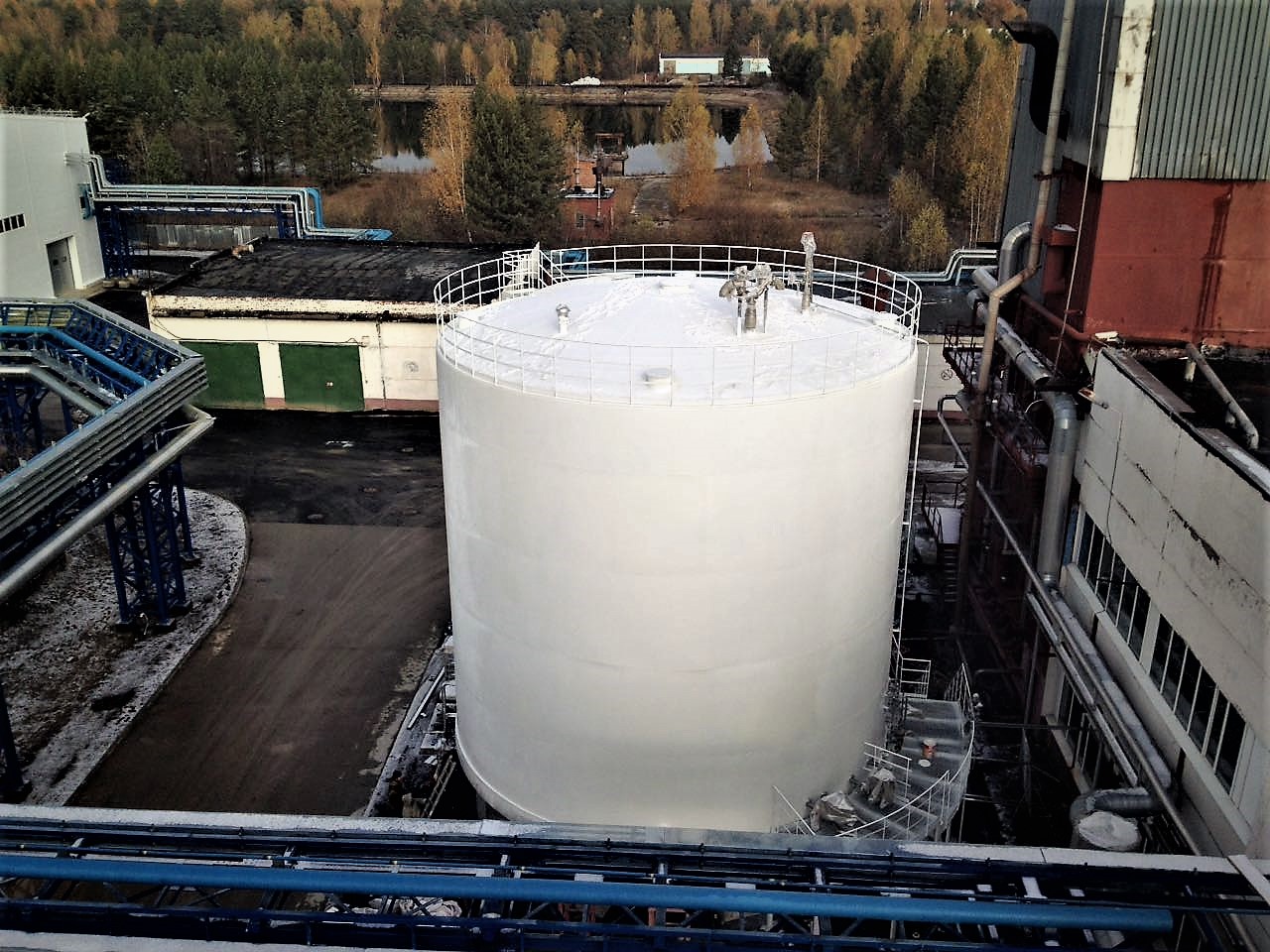
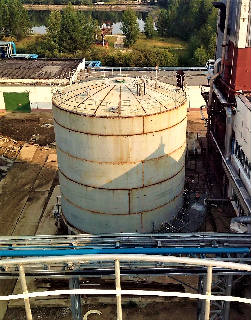
The tank features man-holes for inspection of the inner vessel, thermoinsulating spacing and also ports for perlite loading and unloading
For service and maintenance operations on the manholes, control and safety valves located at the top section (roofing) of the storage tank, it features fenced gangways/platforms. For access to the platforms either a spiral staircase wound on the outside of the jacket or a standalone stair tower located next to the tank is used.
The storage tank is fitted out with process piping, block and safety valves and an array of the control and measuring instrumentation devices.
Filling of the reservoir with liquid oxygen product is achieved via the process piping either from an air-separation unit or from a tanker truck.
A required level of the operating pressure inside the inner vessel of the storage tank is achieved and maintained automatically with a pressurization contour. The countour consists of the pressurizer evaporator, located underneath the storage tank, pressure sensors and regulating valves with pneumatic activators.
Storage control system
Cryogenic storage tank facility features a control system in the form of a local control panel that represents and transforms to the End-User’s top level control system the following signals:
- reservoir parameters (temperature, pressure, level of liquid product);
- condition of the valves (automated block valves - open/shut, regulating valves – degree of opening);
- emergency parameters.
Automated block and control valves may be engaged either from a local control panel or from a distant End-User’s control system.
Cryogenic tank installation procedure
Projects
Engineering company «GazSurf»
Moscow, Volokolamsk highway, 1, building 1
+7 (495) 929 71 48 | info@gazsurf.com