Amine treatment
Overview
Hydrogen sulfide, carbon dioxide, mercaptans are the contaminants which are the most often found in natural gas streams. Due to high corrosion impact on the carbon steel equipment and toxic pollution these contaminant are required to be removed (sweetened) from the natural gas stream. Amine sweetening process is the most common method for removing of H2S and CO2.
Application of the amine sweetening process:
- Removal H2S, CO2 and partially Mercaptans
- Sweetening of NGL
- CO2 recovery from syngas
- CO2 recovery from exhaust gases
Process description
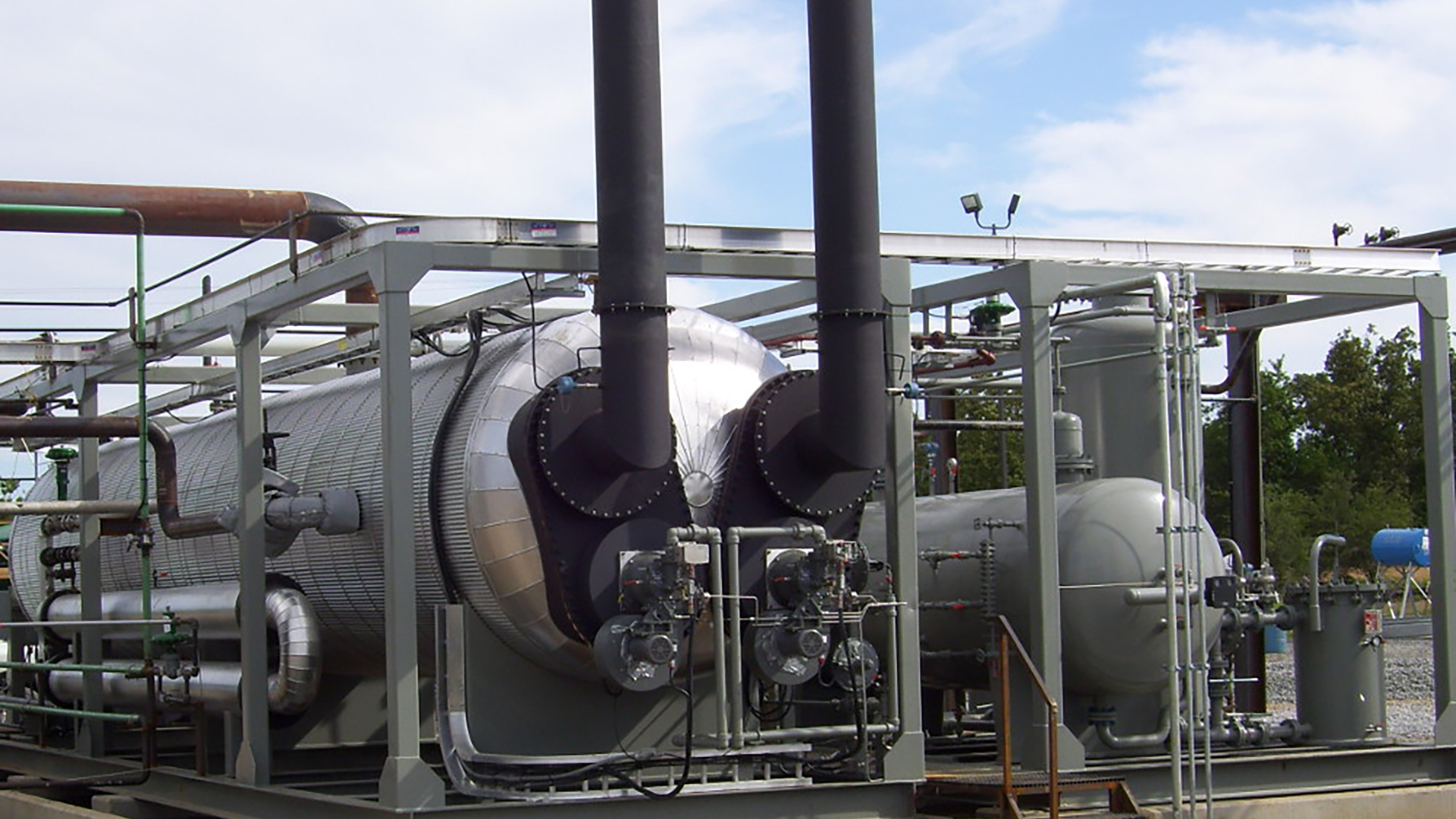
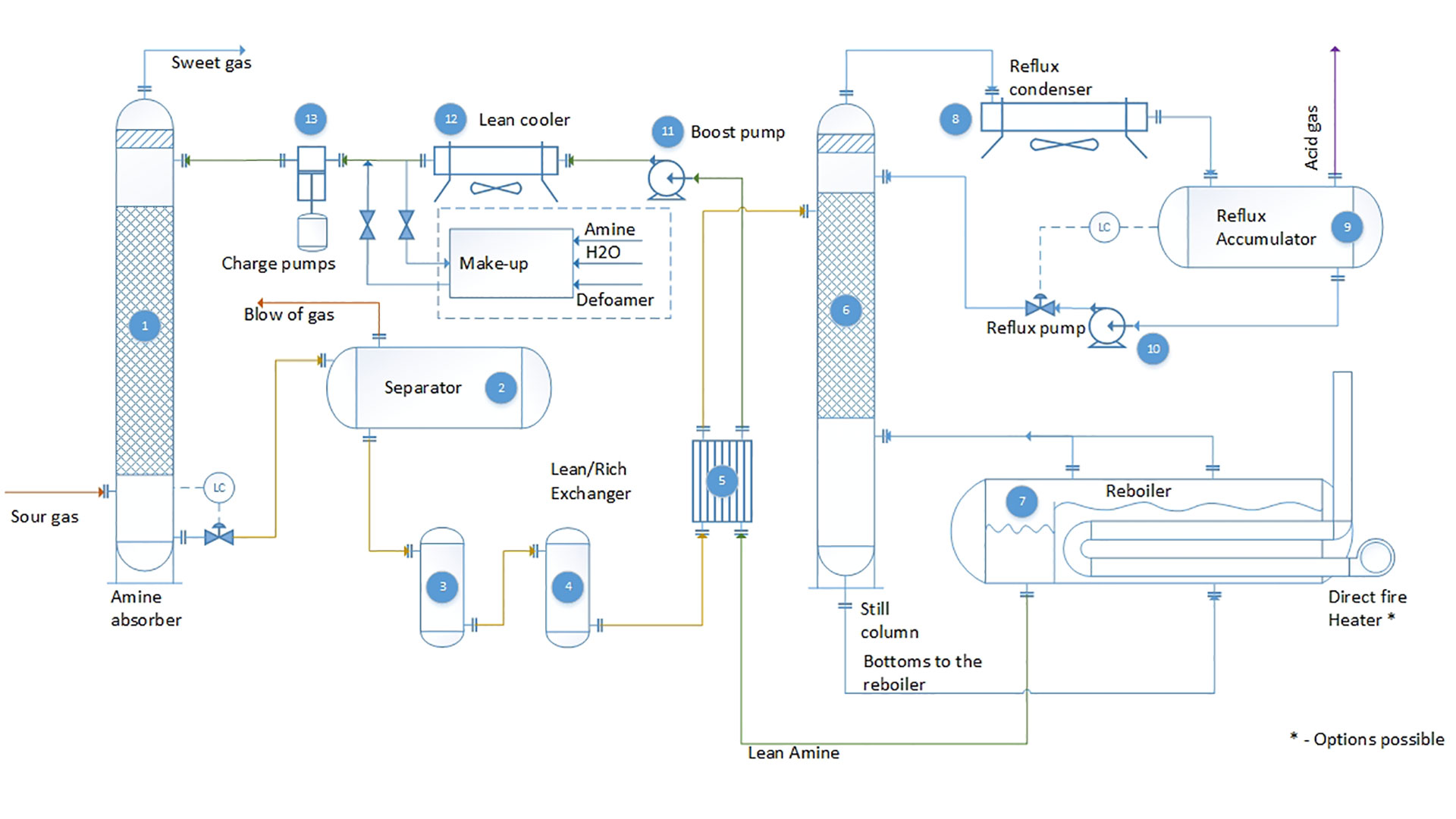
Gas enters the lower section of the amine contactor (1) moving to the top of the vessel gas contacts with amine solution on the surface of contact devices (random packing or valve trays) Contact section usually consists of 7 theoretical stages. Sweetened gas exits the contact section and flows upward through the extended disengagement stage (3) prior to final separation and exits through the top outlet. High efficiency mist eliminator device reduces solvent losses due to the entrainment. Amine contactor is equipped with temperature transmitters to monitor the temperature bulge through the height of the vessel.
Rich amine is level controlled from the lower section of the amine contactor. Light HC are stripped from the solvent due to the pressure drop and are separated in the
Rich amine from
Rich amine is further heated in the regeneration still column, by heat supplied from the reboiler (7). The steam rising through the still liberates H2O and CO2 regenerating the amine. Steam and acid gases separated from the rich amine are condensed and cooled, respectively, in the reflux condenser (8). Condensed steam is separated in the reflux accumulator and returned to the still. Acid gases may be vented, incinerated or directed to a sulfur recovery system.
Hot regenerated lean amine is cooled in a solvent aerial cooler and circulated (pump 12) to the contactor tower, completing the cycle
Rich amine is further heated in the regeneration still column, by heat supplied from the reboiler (7). The steam rising through the still liberates H2O and CO2 regenerating the amine. Steam and acid gases separated from the rich amine are condensed and cooled, respectively, in the reflux condenser (8). Condensed steam is separated in the reflux accumulator and returned to the still. Acid gases may be vented, incinerated or directed to a sulfur recovery system.
Hot regenerated lean amine is cooled in a solvent aerial cooler and circulated (pump 12) to the contactor tower, completing the cycle.
Amine selection
Type and concentration on the amine solvent are critical parameters for the definition of the amine sweetening process. Following are typical amine concentrations of water/amine solutions:
- Monoethanolamine: About 20 % for removing H2S and CO2, and about 32 % for removing only CO2
- Diethanolamine: About 20 to 25 % for removing H2S and CO2
- Methyldiethanolamine: About 30 to 55% % for removing H2S in presence of CO2, removing H2S and CO2 in case of solvent formulation (piperazine)
- Diglycolamine: About 50 % for removing H2S and CO2 and 70% of “light” Mercaptans
Projects
Engineering company «GazSurf»
Moscow, Volokolamsk highway, 1, building 1
+7 (495) 929 71 48 | info@gazsurf.com